This means holding them at the edges until you shape the tyre profile. Then the casting should be held by the opposite faces of the tyre between a pair of discs - especially if you are using a form tool.
MY PREFERRED METHOD
Measure the casting and make a sketch of its
cross section to find the safe areas outside the tyre where turning shoulders can be cut. Also draw the tyre to show clearances in front and behind the tyre.
I usually remember to send copies of my 6" x 4" workshop card with the castings.
The wheel surface may be spoilt by small errors in machining the surface of the hub. Castings may have very small variations in thickness one to another - so to be able to face the hub just right, leaving just a little of the rounded shoulder (as in most locos though not where some had planed the hubs down to a sharp edge), you need to machine the hub surface in tiny final cuts until it looks right by eye. Then the front of the tyre is a fixed amount below that, and finally the tyre thickness cut at your chosen distance from the front. If you feel tempted to do this the other way round, making the final cut of back of the tyre when you first mount the casting in the lathe remember that you lose the opportunity to fine tune the hub surface later if it is not exactly where you expect it to be.
PROCEDURE:
1. MAKE A SMALL SHOULDER ON THE BACK so you can mount the casting front outwards for the
next operation.
1. Mount the casting BACK OUT on its cast shoulder and cut a small shoulder on the outer edge in the safe area outside the flanges.
Make the shoulder 0.5 mm closer to the front than the back of the final wheel and at a diameter of the final wheel dia. across the flanges, plus 1.0 mm for 1.5 mm
wide flanges and 0.5 for 1.0 m wide flanges (See diagram 1).
(See a turning diagram marked up for a Gauge 0 Fine casting.)
2. TURNING THE FRONT OF THE CASTING
Mount the casting FRONT outwards on your new shoulder in a 4 jaw chuck centring with a dial indicator.
Take a cut over the tread at about 0.5 more than the final diameter, and just short of the root of the flange – usually about 1.2 mm out from the chuck face.
(See diagram 2). (When the casting is reversed for the next step this will hold it parallel
to the front, as well as saving some wear on your form tool if you are using one.)
Skim the hub just enough to make a level surface. There may be a hump in the centre (for contraction allowance) to be removed.
Face the front of the tyre (the turning card will show how far it is below the hub). It is at this stage that you will start to see the benefit of
using a vee pointed tool end on to the work, the depth of cut reduces to nil as you reach the inner edge – which cannot then crumble as it might with
a shaped insert. For best appearance use a slow rate of feed. Be very careful not to cut into the weights of some wheels which project beyond the tyre
as in the LNER A3.
Turn the chuck by hand to deburr the inner edge with a hand scraper.
Centre with a Slocombe drill and drill (eg with a Titanium coated stub drill) – this will need to be undersize for reaming to the final size later.
Eg for 1/4" drill 6.3 and ream 6.33 or 6.34 for a press fit.
3. FACING THE BACK
Mount the wheel BACK OUT, centre with the dial indicator, face across the whole wheel to give the tyre thickness of your chosen standard. (That is 6.0 for
G1MRA standard, 5.0 for G1MRA Fine, 3.5 for Gauge 0 Guild Fine, or an exact proportion for 'dead scale' models.
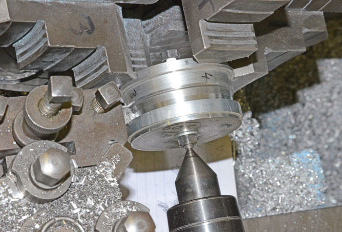
4. TURNING THE TYRE PROFILE
Mount an aluminium backing disc in the jaws of the lathe (See diagram). This is a double sided disc with a step turned on the inner face to sit on the corners of the chuck
make the back step at least 50 mm dia to help reaching in with spanner to a nut on the back of the mandrel), its outer face is to the nominal diameter of
the wheel, drilled as a loose fit for your mandrel.
To make sure of an accurate back-disc face (so that the wheels are vertical to the axles), every time that you put it in the lathe, mark the whole face with a felt tipped pen and machine off just enough to remove the ink all over.
Pass the mandrel spindle through from the back, then on the front place the casting, front disc and nut. Gently rest the centre of the live tail-end centre into the 'pipped' centre in the end of the mandrel bolt.
Make sure that the front disc is sufficiently recessed to clear the hub so that all the grip is on the tyre sides.
As the casting is slightly loose on the mandrel, finger tighten the nut. Use a dial indicator to find where it is off-centre and lightly tap the edge of the casting with a
hammer until it is central and then tighten the nuts with spanners.
(You will soon find out by experience how tight is 'finger-tight' - if it is too tight the casting will not move when you tap it, if it is too loose it will not hold its
position).
Make several cuts at the appropriate angles, or make one more accurately repeatable but slower cut with a form tool (if your lathe will turn slowly enough). If using a form tool, line it up carefully, lock the saddle and turn slowly to size. I use about 0.03 mm/rev feed at about 40 to 70 rpm, depending on diameter. Hand turning the chuck with the lathe in neutral for the last little bit gives a smoother burnished finish. Wheels gripped at the centre only may slip or break the spokes during turning so ALWAYS GRIP BETWEEN DISCS WHEN TURNING THE TYRES, otherwise breakages are at your risk.
Slip off the front disc, replace it with a smaller spacer across the hub, recentre, retighten, and with the lather in neutral turn the chuck by hand to remove a small bevel from the front edge of the tyre.
MOUNTING WHEELS ON AXLES
See under
'AXLES' for a note on adhesives
and press fitting sizes. For press fitting I make discs recessed to fit the wheel exactly with just the right extra allowance at the
hub to prevent either wobble, if too little or axles pushing through if too much. In the back I leave a 10 mm dia stem to hold the discs central. This could
be forced on between the lathe chuck and back post, though I prefer to use a machine vice converted with new jaws having
10 mm holes dead opposite to each other. Slots are milled in at 90° the width of coupling rod pins for quartering. The press discs are very handy to use as
sizing gauges during turning to make sure the wheels are all the same size.
CARBIDE TIPPED TOOLS,
the sharp pointed shape known as 'roughing' is good
for cast iron. There is little chance of edge crumbling as the cut depth reduces to nil as you finish a cut across a tyre.