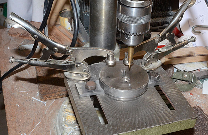
Image shows the pin drilling jig on the table ready for a wheel to be placed with the pin through the axle hole.
The assembly will be lined up with the pointer on the marked position of the crank pin hole - and bolts tightened up.
The wheel is held in position by the drill clamps.
POSITIONING AND DRILLING THE CRANK PIN HOLES
The axle hole positions have already been determined not by a dimple, but by their being in the centre of the wheel when it was mounted in the lathe, centred and machined.
The crank pin holes are positioned relative to the axle holes.
On the bench: insert a marking out centre plug into the wheel and draw a line through the centre of the axle and the boss.
Not being perfectly in line has a cosmetic effect and does not affect the running.
Drawing lines on all the wheels of a set helps to line them up for drilling.
I set my callipers to the amount of the pin throw and match that up with a pair of dividers.
With one end of the dividers in the pip in the middle of the centre plug, scratch across the line which you have just drawn.
That sets the radius of the crank pin hole and must be exactly the same for all the driving wheels on a loco.
(You only need to mark the radius on the first wheel, the others will be the same as long as you do not move the jig).
Fix your wheel holding jig on your drill stand table, lining the first wheel up with your round pointer with its tip where the drawn and scratched lines cross.
Bolt it down firmly so that the other wheels in the set all have the same crank pin throw. Clamp the wheel firmly on top of the jig and drill the hole.
Remember that drilling a hole full size in one go usually makes it slightly oversize. Drilling about 0.1 mm under size and then drilling or reaming to final size is more accurate.
For the rest of the wheel set use the round pointer just to line up with the mid line of the boss - the distance is already set.
Notes:
Marking out centre plugs: these are lengths of round bar to fit into the axle hole while you are marking it out.
Length is the thickness of the wheel through the hub, dia is the same as the axle. For hub insulated axles make another plug for use before insering the bush.
'Pip' one end of the plug with a spotting drill. This gives a smaller point at the centre than a conventional drill which leaves a flat centre.
Spotting drill. I use a 4 mm dia spotting drill from https://uk.rubix.com
Round pointer. This is just a length of round brass say, 50 mm long x 8 mm dia which has been turned to a long point in the lathe. It can be used in a pillar drill for lining up work before
swapping it out for an actual drill.
Wheel holding jig. This is any flat metal surface which can be bolted to the pillar drill table and which has a fixed central pin the same size as your axle.
For small wheels I use a metal disc mounted on to a length of flat strap. For larger wheels I use a single bigger disc which reaches across the table.
The central pin stays in exactly the same position for each wheel.
Reamers: the taper of hand reamers makes them easier to feed into holes machine reamers which are otherwise similar.